Diary 2023
Black and gold beauty
This description of the rebuild of an historic Mk.VIII KTT Velocette reveals the details and processes involved in returning this beautiful machine to its original specification.
Words: ROB DRURY - Photographs: GARY CHAPMAN
Article also published in October's edition of The Classic MotorCycle, see: https://classicmagazines.co.uk/issue/View/issue/TCM202310/october-2023
In the summer of 2008, I was asked to assess the contents of a lock up garage in Cumbria, where there was a substantial quantity of overhead camshaft Velocette spares, and which included a dismantled Mk.VIII KTT. I made a report and was then asked to make an offer, which was accepted, so I returned to collect the contents.
The Mk.VIII engine had been installed in a Norton Featherbed frame, so it was removed and the clearance of the garage later revealed the Dominator engine, so that there was another complete motorcycle for the owner to sell.
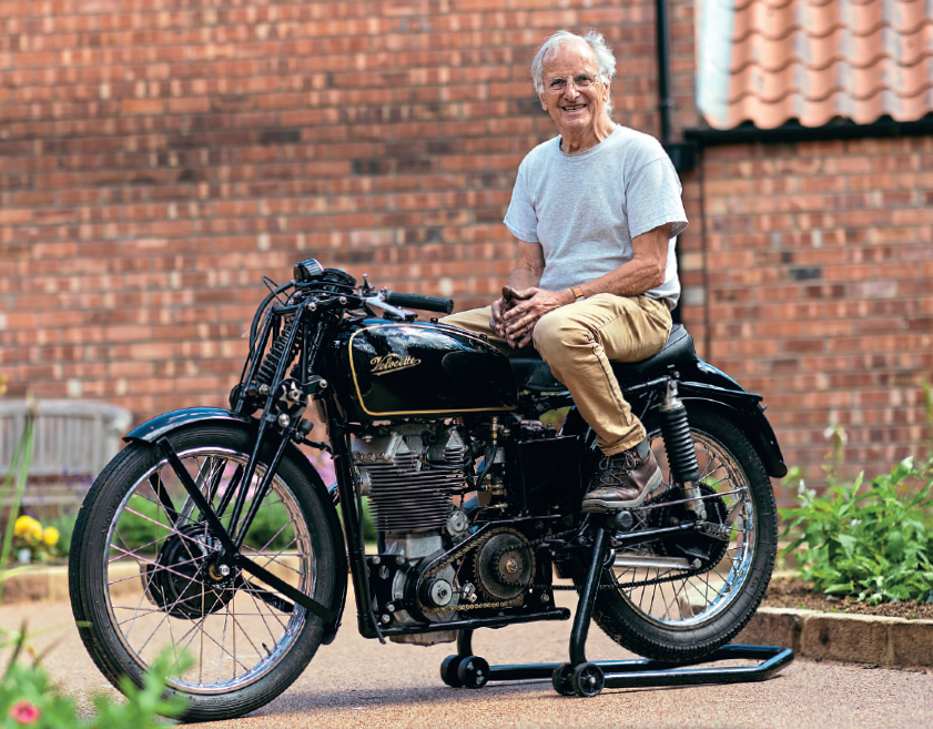
A sort through the cache revealed that all of the principal parts of KTT817 were present. The engine and gearbox with the correct numbers and many parts, including the genuine front and rear hubs, were there. I was pleased to spot the original Amal TT carburettor with its distinctive spigot on the flange.
Complete overhaul
The previous owner had clearly embarked upon building a special and the bottoms of the front forks had been cut off with plates welded on to replace the bottom lugs. The forks were dispatched to Ray Daniels for retubing and a complete overhaul, and came back ready to fit.
The frame had been similarly molested and certain lugs were missing. I was fortunate to have a frame drawing and good machining facilities, so, working with the help of my friend and experienced machinist John Raby, we were able to dismantle the frame, restore existing lugs, obtain others and retube the frame using T45 tube. It was brazed together by a professional frame builder.
A mudguard blade of the correct width and radius had side valances added to replicate the rear mudguard fitted on pre-Second World War Mk.VIII KTTs.
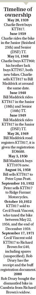
The oil tank was missing but I had retained the patterns for these from when I used to manufacture them, so was able to make a new oil tank. Similarly, I had retained the megaphone patterns, so that was quite easily reproduced. It incorporated a reverse cone that I had developed to meet noise regulations and promote clean carburation.
An exhaust pipe to the exact shape was made by a specialist in Leeds who packed the tubes and bent them under heat to obtain the graceful curves.
I already had some handlebars made to the correct specifications for Mk.VIIIs to hand. The Bowden clutch and brake lever clamps were refurbished and new aluminium levers and pivot pins fitted. The handlebar mounting clamps were missing, so new ones were machined from billet aluminium and painted black.
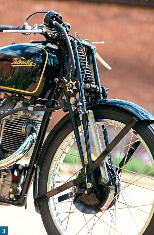
The original Amal TT carburettor was discovered with the machine.
Garage clearance
During this period of sorting things out, I was able to work out the bike's full history of ownership through various documents that had accompanied the garage clearance. The KTT had been sold when new to well known Leeds, Yorkshire, rider Charlie Brett, who had ridden it in both the Junior and Senior TT in 1939. KTT817 was the bike that Charlie's brother Jack started his racing career on in 1946. The younger finished seventh in the atrociously wet 1946 Senior (500cc) Manx GP on the 350cc KTT. Jack went on to become a works rider for Norton and AJS, winning one Grand Prix, the 1952 Swiss 500cc race, on a Porcupine.
Among the spares came a genuine AJS 7R tank and the documents included letters which put me onto the trail of the original fuel tank. I discovered that a swap had taken place - the Mk.VIII tank for the AJS one during the 1970s, and although I know where the original tank is now, it is not available. I eventually found a genuine fuel tank, had it professionally repaired and then repainted by Clive White at Rapier Paintwork of Hull. Clive also painted the frame, rear mudguard and oil tank.
Two of the letters in the file of correspondence referred to a DOHC cylinder head that came with the stuff, and led me to James Bowen, who had sold it to Richard Brown. This was fortunate indeed as James and I have become good friends in our shared interest of Velocettes and banjos.
Curiosity compelled me to have a look inside the engine - this revealed it to be in excellent condition, though I did not like the ugly aftermarket Wellworthy cylinder barrel that was fitted. I decided to do no more to the engine until I was ready to start the rebuild properly, but I did manage to buy a brand-new genuine Mk.VIII KTT cylinder barrel in anticipation of that day.
The original gearbox was found but had been dismantled, but I was not able to find the internals. The case (7-5297) was in good condition with no damaged threads. I had it vapour blasted clean. Among my spares, I found an excellent TT ratio cluster in a 12R shell. These fitted straight into the prewar shell, but the sleeve gear had to be shortened. Good internals and selectors were found and an 'up for up' cam plate fitted. New bearings and seals were fitted.
Owner Drury made the oil tank. Note the remote-mounted float bowl.
In March 2020, I found myself in isolation (along with the rest of the nation) and had to revise my plans for final assembly. I was fortunate enough to get the freshly painted frame, subframe, swinging arm and rear mudguard back before things got really difficult. My original plan was to not start the rebuild until everything was to hand. At this point, the hubs were still being painted and would then need building into rims and tyres fitted.
After laying out all of the frame parts and the front forks, I started to loosely assemble. The swinging arm and subframe was fitted to the main loop, front forks and a pair of Oleo rear suspension units installed, nothing was finally adjusted. I fitted the rear mudguard loosely to the frame as a place of safety against accidental damage. The gearbox was fitted into the rear engine plates and loosely installed in the frame.
It was time to find all the ancillary parts that have been collected for the project. The handlebars were ready to fit, with alloy levers and cables attached. A new Andre steering damper was put in place and the anchor brackets made, ready for painting. Footrests needed a bit of straightening up and painting and then were fine. The gear lever was good but needed chromium plating. A decent linkage to the gearbox was assembled. The original rear brake lever components were present, but the outer part of the oval foot piece of the brake lever had been cut off. It appears to have been a common practice at the time. I cut a piece of ¼in steel plate to the correct shape, brazed it to the pedal, cut and filed the additional piece to the correct contour before filing in the serrations and the border. It looks well now that it's painted.
The rear brake cam lever was missing but friend Peter Miles gave me a genuine one that needed a repair to the square hole that the cam spindle fits into, this was easily done. The tachometer had been fully overhauled several years ago and only needed a mounting bracket making. I had set aside a Webb handlebar mounting clamp for the job and making the mounting bracket was quite simple. Johnson's Cables made me a tachometer cable with a thick outer casing to replicate the ones used.
It was now appropriate to prepare the bottom end of the engine to be installed into the frame. Things could then be fixed properly and a good many jobs could follow from it. I had already concluded that the engine was in such good condition that it could be reassembled and used. Everything needed close inspection to confirm this. The crankcases were carefully cleaned manually with a brass wire brush and brake cleaner, achieving a good standard and revealing no significant damage. The engine mounting holes had steel sleeves inserted and two of them went through both cases to provide alignment dowels. The crankcase spigot was absent and one can only speculate whether the dowels were fitted as a repair or as an improvement. The main bearing bosses were intact and not sleeved, as often is the case.
The retaining screws for the oil pump had been locked in an unorthodox manner and I decided to test the pump in-situ and if okay, to leave well alone. The engine internals showed that there had been adequate lubrication. The pressure test showed the pump to be capable of delivering in excess of 40lb psi and scavenging efficiently. The pressure was set at 10lb psi running pressure.
One oddity was the lower bevel housing made of aluminium with a larger body than standard, rather like the works ones with bearings installed. It turned out to use a standard bush and would have been exchanged for a standard item but for the discovery that the spigot into the crankcase was a larger diameter.
The flywheels and shafts were carefully examined, there was no damage to them, the big end had no play and the small end bush was excellent. I pulled the bearings off to test the assembly for accuracy and was pleased to note that they were a tight fit on the main shafts. The flywheels were accurate about the crankpin but slightly out of parallel. This was corrected to within the recommended maximum permissible run-out. The bearings were cleaned in the ultrasonic bath, a roller removed and the inner tracks carefully inspected. All looked well, so the bearings were refitted and the flywheels reassembled into the crankcases.
The original front forks were restored by specialist Ray Daniels.
The lower bevel housing was mounted onto a mandrel in the lathe and a cut taken across the flange to ensure that it was square to the bore and flat. The bush was faced until the bottom bevels were correctly in mesh and the unit was bolted up to the crankcase with a face joint and a smear of jointing compound.
The newly overhauled BTH KD1 magneto was fitted with four new studs and reduced hexagon nuts for ease of access. The filter in the rear timing cover was cleaned ultrasonically, the magneto driving pinion lapped to its sprocket and the inner timing cover fitted to the crankcases. It was time to install the bottom end of the engine into the frame, using a set of new high tensile bolts and nuts supplied by Grove Classics. Undrilled front engine plates were carefully aligned, drilled with no clearance on the holes and fitted, to be painted later.
I made new through-studs for the oil tank, found the appropriate rubbers and made the special jacking screw that is just in front of the seat tube. It fitted up very well. New feed and return lines were made, the feed utilising a longer fitting into the crankcase to provide better access and a smoother approach. The return using a banjo and copper pipe for better flow.
It was a good time to start preparing the cylinder head to go back on. It was very dirty and extra material had been welded to the bottom fin in an attempt to make it match the Wellworthy cylinder barrel. Dismantling revealed nearly everything to be in good condition. Last built in the 1970s, all of the studs had been replaced with cap head screws (they seemed to be such a good idea at the time) which were all ferociously tight. The valves and seats in the head were dirty but the valve guides were good. The cam was the final iteration, a K17/11A with lift so high that there is a scallop in the head to permit installation. To assist with the extra lift, the valve springs had been packed up, creating more pressure that would result in excessive wear on the cams and followers. With the cam removed, the camshaft bearing was checked and restored to good order by fitting new rollers. All else appeared well.
The job of removing the extra welded-on material was hard, dirty and unpleasant, but succeeded in restoring the bottom fin to its correct dimension and shape. The head was vapour blasted and the restoration will pass unnoticed.
A good, used ex Veloce K17/8 cam was fitted, along with new bearings for both ends of the camshaft. The upper bevel was carefully meshed with the crown wheel and the assembly was reunited with the cylinder head, using a pair of rockers that had been built up with stellite and reground. The radius on the cam followers had been increased to ?in, so they are better than new. The new valves were lapped in and installed with light coil springs, ready for timing the valves.
The four crankcase studs were of differing lengths, so four new ones were made by shortening and rethreading Mk.II KSS ones. New cylinder head studs were made from EN16 and the threads in the special cylinder head nuts were run through with a 5/16in BSCy tap.
The cylinder barrel was a brand-new item but the groove for the advance/retard cable had not been machined. It was set up in the milling machine and the grooves were cut with a ball-nose end mill and finished with a hand riffler. It was installed with the 'pool' petrol piston with new piston rings and no compression plates.
While the cylinder head was away being vapour blasted, I had time to sort out a seven-plate clutch and get it installed, with new parts where appropriate, including the three parts of the thrust race, springs, shims and locking plate. The clutch was fitted with a new primary chain and a brand-new engine shock absorber assembly lapped onto the engine main shaft - the last one in captivity.
Four special fuel tank mounting bolts were machined from stainless hexagon bar to a drawing kindly supplied by Peter Miles. They are shouldered 3/8in BSF bolts with a waisted centre section.
A timing disc was set up and TDC accurately set using the positive stop method, the piston was set to TDC with the lower Oldham coupling slot 'fore and aft'. The vertical drive shaft had new Oldham couplings carefully fitted and the drive shaft assembly tested for vertical clearance with the cylinder head lightly nipped down. The rockers were installed and the tappets set to the checking clearance of .020in. There being no clear timing marks, the cam was rotated until both valves were equally open with the Oldham coupling 'fore and aft'.
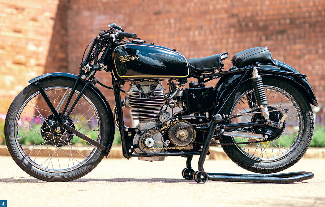
Skimpy chainguard was produced to original drawings. Note the valanced rear mudguard, as fitted to pre-Second World War Mk.VIIIs.
When the cylinder head was fitted, the opening and closing events were within the range of adjustment at the crown wheel. They were:
- Inlet opening 58 degrees BTDC (three degrees early)
- Inlet closing 65 degrees ABDC (correct)
- Exhaust opening 80 degrees BBDC (five degrees early)
- Exhaust closing 48 degrees ATDC (three degrees late)
I believe that these figures will be entirely satisfactory, any fine adjustment at the crown wheel to correct one small error will make another event worse.
The use of light springs offers the opportunity to check the valve/rocker geometry - that the valves are the correct length and that the axis of the rocker at half lift is square to the valve stem.
The valve clearances were set at .008in inlet and .012in exhaust for running, in recognition of lower expansion rate of the valve material 21-4Na nd that the engines will not be expected to run at 7000rpm for four hours continuously.
Rather than adopt the 'works' method of spoiling the threads on the four crown wheel studs, four special spigot nuts, with provision for lock wiring, were made and fitted.
The ignition was timed at 36 degrees BTDC, advanced. New hairpin valve springs were fitted and the cylinder head made ready for final assembly with a set of new studs to retain the rocker covers. The cylinder head was nipped down onto a freshly annealed head gasket.
The new exhaust pipe plus sundry other parts had been taken to Prestige Electroplaters for plating, on the understanding that they will be ready for collection before Christmas.
By the September, Steve Lomas had completed the rebuild of the wheels and fitted new tyres. "They were installed, a new rear brake rod made and a new cable stop for the front forks. lhe front hub is a works type with a bolted-on brake drum, as fitted to early production Mk.VIIIs. I was very fortunate in obtaining a pair of new taper rollers from the VOC spares scheme. Both hubs are painted in gloss black instead of the semi matt silver later adopted. The rear hub has a brand-new brake drum/sprocket fitted.
An aluminium spacer for the carburettor with location spigots was made, along with longer studs and the original Amal IT carburettor fitted, with new cables.
The cylinder head steady was missing, so a new one was machined from HE30 aluminium with flutes milled into the sides for a bit of style.
Prestige Electroplaters finished the work early and in December, I collected the parts, all done to their usual high standard. By the following day, many were fitted, lifting the bike's appearance.
Next, the plated oil drain pipes were fitted, with special spigot nuts made to fit the counter bores that had been drilled for the cap head screws. The oil pipe that feeds the two jets oiling the upper bevels and cams was also fitted. The engine was now complete and ready to start. A new rear chain and final drive sprocket was installed. The frame of the small Lycette type saddle needed surgery to make the mounting points match the frame. Exhaust brackets were made and fitted.
There was a slight dilemma over which rear suspension units to fit, as I have a pair of the original Dowty Oleopneumatics and a pair of replica units that I had made with 'coil over oil' units inside. I decided that my replicas would be more reliable, found some suitable rubber gaiters and fitted them. They look well, though not exactly right and the originals can be fitted at some time in the future.
I had a pair of the original large-bodied lever petrol taps, which were fitted and new fuel lines made. The fuel level was set in the remotely mounted float chamber.
I had been mindful all of this time that I needed a new front mudguard, but was having little success in finding one. I discovered that I did have one of the correct cross-section, radius and length, but that a section of bead had been damaged in the rolling process. There was little choice but to repair it and it turned out well. A new centre bracket was made, along with a pair of flat aluminium stays. All of the above have been painted by Clive, are fitted and look excellent. The stays were originally riveted to the mudguard but this makes them very awkward to handle and fit. I altered the head profile of some suitable coach bolts, made square holes in the guard and stays, fitted them and they look like rivets.
In January 2021, the oil tank was filled and the engine spun on starting rollers until oil pressure registered on a temporary gauge, petrol added and the engine started promptly. It sounded very well. This is always something of a relief, particularly when the job has been protracted. The final jobs can then be completed with a relaxed frame of mind.
An oiling device for the primary chain was made and fitted. It incorporates a nylon brush to distribute oil directly onto the lower run of the chain just in front of the clutch chainwheel. It's an arrangement that should prevent the oil being flung off before it can reach the rollers.
I had become anxious about the linings fitted to the front brake shoes on the replica front brake plate, having read about experiences of them coming off. When I had machined them to drum size, one lining was thinner than the other. After discussing the matter with Ian Campbell of Classic Brake Services, the brake plate was remounted in the lathe, the linings turned off and metal removed from the face of the shoes until they were both concentric to the spindle. The assembly was sent off to Ian and returned with Kill thickness liners, bonded, riveted and turned to size. I am now content that the front brake can be used with safety.
The primary chainguard was missing but Peter Miles kindly supplied drawings. It was necessary to make a former to produce the radiused stiffening edge. A replica guard was made, painted and fitted. I also made one for Peter's MkV111 KTT.
I had left the bum pad until last, so that I could concentrate my mind on it without distraction. Moseley air cushions were the original fitments and the replicas, made by RK Leighton, are good quality but foam filled, so lack the 'saggy' appearance of the original. Replacing the foam 'vsith a combination of felt and an air bladder has created a fair result, I suppose that it will take some use for it to adopt the period 'saggy' look. lhe fabric mounting flaps at each end of the bum pad are fixed to the mudguard with sheet metal straps, secured by small coach bolts.
I had the original buff logbook and with the aid of the dating offcer of the VOC and clear photos of the relevant numbers, was successful in reclaiming the original registration. To make the bike legal for road testing, a rear numberplate was designed, made and fitted. I was keen to use only the two existing rear mounting bolts and not drill any extra holes in the mudguard.
The first road test - in May - quickly revealed the carburation to be very rich at the throttle valve cutaway. The fuel tank was removed (access to the carburettor is poor) and the slide changed from a No.4 to a -\0.5. A further road test showed a big improvement but still too rich. The cutaway was changed to >.'0.6. lhe road test proved the carburation to be very close, so any further adjustments would be minor. The 'works' type two-piece front hub made for a particularly powerful but well-modulated front brake, as Ivan Rhodes had predicted.
With that, the project was deemed finished, with one of the early Mk.VIII KTTs returned to as near as possible to the condition it was supplied to Charlie Brett, 84 years ago.